 Reference Drawing Tools
- General Settings
- Step-By-Step
- Tips and Tricks
- Related Tools
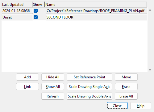
Last Updated : Shows the date and time that the reference drawing was imported. This will only show if the reference drawing was created using Link Reference Drawing. All other reference drawings show ' Unset ' .
If this box is checked (
), the reference drawing is visible in the model.
If the box is not checked (
), the reference drawing is not visible in the model.
Name : The file path or name of the drawing that has been added as a reference drawing. If there is no file path associated with the name, that means the file was added from the drawings list using the Add button. If there is a file path associated with the name, that means the file was added using the Link button
Add : You can add a detail , job standard detail , reference drawing or 2D erection view as a reference drawing in Modeling . See the steps below:
1 . Press the " Add " button
2 . The Select One Reference Drawing window opens. Select the drawing type ( '
Details ' or '
2nd_Floor

Optional for details : The " Hide ... " button lets you adjust which members are shown on the selection list when " Details " is the selected drawing type. The " Show All " button shows details that are not current.
3 . Locate - Pan - Return mouse bindings become active along with various Locate options. The reference drawing is shown on screen.
Alternative 1 : Left-click ( Locate ) where you wan the reference drawing to be placed..
Alternative 2 : Right-click ( Return ) to cancel adding the reference drawing.
Note : If you have previously placed the drawing you selected in step 2 but have since erased it, the drawing will go to the location it was previously placed. If you want to move that drawing, use " Move ."
4 . The newly added reference drawing will be shown in the model. On this window, you will find that the name of the drawing you added is listed and that " Show " is checked (
Link : You can link to .dxf, .dxb, .dwg, .dgn or .pdf files in Modeling . The externally-linked drawing is added to your 3D model in the same manner as it is when you " Add " a reference drawing.
1 . Press the " Link " button
2 . A file selection window opens. Select the file you wish to import ( .dxf, .dxb, .dwg, .dgn or .pdf ). The selected file is converted into a reference drawing.
3 . Locate - Pan - Return mouse bindings become active along with various Locate options. The reference drawing is shown on screen.
Alternative 1 : Left-click ( Locate ) where you wan the reference drawing to be placed..
Alternative 2 : Right-click ( Return ) to cancel adding the reference drawing.
4 . The newly added reference drawing will be shown in the model. On this window, you will find that the name of the drawing you added is listed and that " Show " is checked (
To view the reference drawing: In the Drawing Editor , open the job reference drawing into which the .dxf, .dxb, .dwg, .dgn and/or .pdf files has been converted. The name of the reference drawing will be the name of the .dxf, .dxb, .dwg, .dgn and/or .pdf file, minus the extension. The drawing name will be truncated to 53 characters if the original file that the drawing was converted from had a name that was longer than 53 characters.
You cannot save changes that you make to such reference drawings in Drawing Editor . You can, however, scale the drawing in Modeling when, on the Reference Drawing Tools window ( this window ), you select the drawing and press the " Scale Drawing Single Axis " or " Scale Drawing Double Axis " button. This changes the reference drawing.
Hide All :
Sets all reference drawings that have been placed in the model hidden. All of the drawings that are listed on this window will be set to " ![]() Show ."
Show ."
Show All :
Sets all reference drawings that have been placed in the model be shown. All of the drawings that are listed on this window will be set to " ![]() Show ."
Show ."
Refresh : Updates the reference drawings in Modeling with any changes that have been made inside of Drawing Editor.
Set Reference Point : Allow you to change the insertion point that is used when you " Add Reference Drawing " or " Move " a reference drawing. The actual Drawing Editor drawing will change as a result of this operation. The drawing's current position in the model will be unaffected. See the steps below:
1 . Click the Name or Last Updated date to select the Reference drawing. Select the " Set Reference Point " button.
Note : The text may be highlighted or the section may be underlined in blue to show which drawing is selected.
2 . The status line prompts, "Verify reference drawing reference location." A reference point symbol identifies the reference point's location on the drawing. Yes - No mouse bindings become active.


reference point symbol Alternative 1 : Left-click ( Yes ) if the reference point is where you want it, and you want to end this operation.
Alternative 2 : Right-click ( No ) to relocate the reference point.
3 . Locate- Pan -Return mouse bindings become active along with various Locate options.
Alternative 1 : Left-click ( Locate ) at the location where you want the reference point located.
Alternative 2 : Right-click ( Return ) to cancel this operation and keep everything as it was.
Scale Drawing Single Axis :
This invokes the Scale Drawing Single Axis tool. This tool allows you to scale drawings that you
Scale Drawing Double Axis :
This invokes the Scale Drawing Double Axis tool. This tool allows you to scale drawings that you
Move : Allows you to reposition a reference drawing in the model. See the steps below:
1 . Click the Name or Last Updated date to select the Reference drawing. Select the " Move " button.
Note : The text may be highlighted or the section may be underlined in blue to show which drawing is selected.
2 . Locate- Pan -Return mouse bindings become active along with various Locate options. Select the Locate option that you want. The reference drawing will be moved based on the drawings " Reference Point ".
Alternative 1 : Left-click ( Locate ) at the location where you want the reference drawing to be placed. The reference drawing is moved.
Alternative 2 : Right-click ( Return ) keeps the reference drawing at its original location.
Erase : Removes the reference drawing that is selected when the button is clicked.
Click the Name or Last Updated date to select the Reference drawing. Select the " Erase " button to remove the selected drawing.
1 . Click the Reference Drawing Tools icon, which is pictured above. The icon can be found on the Tools page > Reference Objects section as well as the Import/Export page > Drawings section.
Alternative: Invoke Reference Drawing Tools using the Find Tool by searching the command name and clicking the icon, which is pictured above.
Learn more about alternative methods for launching commands.
2 . The Reference Drawing Tools window opens. Click the Link button to import a new reference drawing or the Add button to place a reference drawing.
3 . Click the Close button to exit the Reference Drawing Tools window.
- Drawing types from Drawing Editor that may be listed are details , job standard details , reference drawings or erection views .
- If " Add Reference Drawing " shows you that the drawing is rotated wrong Open ( Ctrl + o ) a different Modeling view or adjust the drawing in the Drawing Editor before trying to add it again. If the drawing orientation is fine, but you have problems positioning it exactly where you want it, go head and place the drawing anyway, then use " Set Reference Point " and " Move " to reposition it later.
- When a drawing is set to " Show," it may still remain hidden if it was placed outside of the " Depth Checking " limits or if it was placed outside of the current view.
- To restore a reference drawing that has been erased, it must be added again. The reference drawing will automatically be restored back to the location it was erased from.
- The insertion point for a reference drawing can be changed in the Drawing Editor using Verify Reference Point , or it can be changed with this tool, using the " Set Reference Point " button.
- A reference drawing can only be placed once, at a single location in the model. If you want to place the drawing more than once, you need to use Save As in the Drawing Editor to make a copy of that drawing.
- If your imported drawing appears without text or lines in Drawing Editor, open the Layer Panel and hide the PDF Image Layer. This action may reveal text and linework when you press " OK ". That is because some PDF files may contain a white background image. Such a file, when imported into a reference drawing, will appear in Drawing Editor to have no text or lines, since they are assigned upon import to a pen that, like the background image, displays white and is obscured by it.
- Reference Drawings in Modeling (topic)
- Reference Drawing Add
- Reference Drawing Erase
- Reference Drawing Erase All
- Reference Drawing Link
- Reference Drawing Move
- Reference Drawing Refresh
- REFD ( Locate option for reference drawings)

